Loading...
Searching...
No Matches
Installation & Setup
Before you begin
- Review Operating Procedures & Safety Precautions for safety precautions – the GPA35 operates at high power and radiates RF power. Read that page before applying power.
- Confirm your DC supply and cabling can deliver the required input (see Test Setup below) and that RF cabling/loads are rated for the GPA35's output power (Overview & Features – up to 35W / +45.4 dBm).
- Ensure the installation site can provide the forced-air cooling described in Maintenance & Repair (minimum 20 CFM) – do not power the unit without adequate airflow.
Test Setup
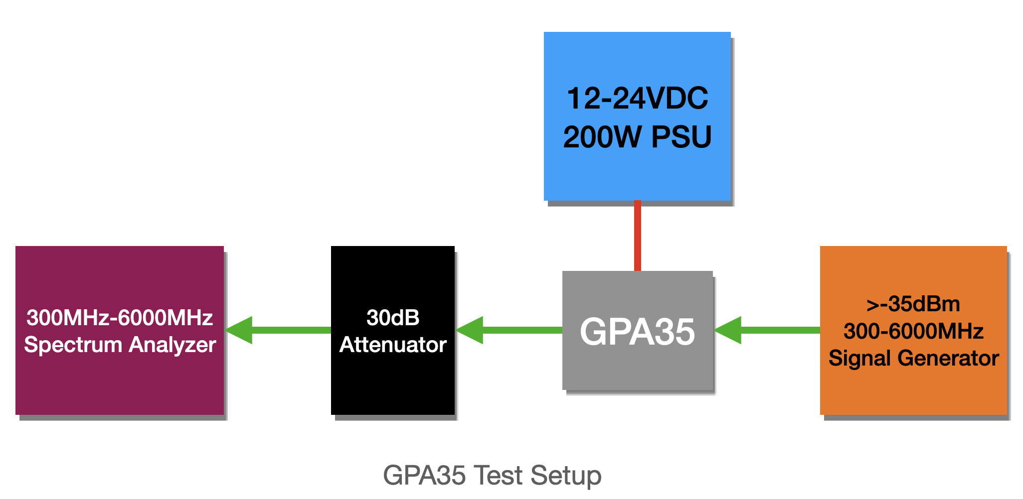
GPA35 recommended test setup
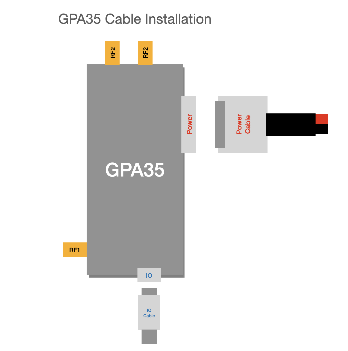
GPA35 cable polarity
1. Mounting
- Mechanical envelope: 1.6in (H) x 2.9in (W) x 5.6in (L), under 7 lbs (see Overview & Features).
- The GPA35 is conduction-cooled with adaptable mounting; the mounting plate can be designed to your system's needs.
- Mount so the heatsink fin airflow path is unobstructed in the direction your installation's airflow moves.
2. Connect RF
- RF connectors are SMA. RF1 is the PA input and RF2 is the PA output.
- Because the GPA35 is bi-directional, RF2 can instead be used as the receive port from the antenna, with RF1 routed to your digitizer.
- Do not apply RF input above the rated input level for your configured gain setting.
3. Connect DC power
- Input range: 12VDC-48VDC (Overview & Features).
- Red is the positive reference; black is ground.
- Verify supply polarity and voltage before connecting – reverse polarity or over-voltage can damage the unit.
- Ensure your supply can source the required power at your configured output level:
| Output Power | DC Power Consumption |
|---|---|
| 35W (full output) | 100-120W (varies with signal bandwidth) |
4. Connect the host interface
- Connect USB-C to your host/monitoring system for telemetry streaming and Configuration via libqynetic control via
libqynetic. - TODO confirm default enumeration/discovery method for the host interface.
5. Power-up sequence
- Confirm cooling airflow is running.
- Apply DC power.
- Confirm the unit enumerates / is reachable from the host running
libqynetic(see Configuration via libqynetic). - Apply an RF input only after confirming the unit is configured for your intended gain/attenuation and RF path setting.
6. First configuration
Once powered and connected, configure the RF path, filter, attenuation, and gain settings via libqynetic before driving RF power through the unit – see Configuration via libqynetic.